HAE floor printer machine can direct to print any format any size machine on wall for decoration and advertising, printing resolution up to 2880dpi
Wuha HAE specializes in R & D and manufacturing of Wall Printing Machine, UV Wall Printer, and direct floor printer, high quality, global services. Floor Printer, Ground Printer, Direct Floor Printer, Direct Ground Priinter Wuhan HAE Technology Co., Ltd. , https://www.whwallprinter.com
0 INTRODUCTION At present, the collection of electric energy data in China is basically manual meter reading. This method requires the meter reading worker to go from house to house to read the number of the electric energy meter and copy it every month or every two months. If there is no one at home, there is no way to read it. Take data. The user's electricity bills are mobilized by computer or hand-made electricity bills, and the method of manual meter reading is also very unfavorable for data statistics. There are also problems such as mis-reading, missed copying, and estimated copying. Nowadays, the development of science and technology also puts forward new requirements for meter reading methods. It requires the improvement of reliability, real-time performance, and convenience of data processing. The wireless automatic meter reading system is an excellent method in automatic meter reading systems.
1 The overall design of the automatic meter reading system The wireless meter reading system is composed of three parts: the monitoring center computer system, the wireless remote meter reading terminal and the GSM wireless communication mobile network. The overall structure of the system is shown in Figure 1. The main function of the monitoring system center computer is to receive the electricity sent by the lower computer, calculate the electricity charge, and then send a short message to the user's mobile phone, and generate and print reports. The remote meter reading terminal reads the meter periodically and sends it to the monitoring center computer. 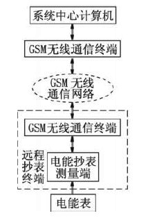
Figure 1 The overall structure of the wireless automatic meter reading system
The module integrates RF circuitry and baseband to provide users with standard AT command interfaces, providing fast, reliable, and secure transmission of data, voice, short messages, and faxes for user application development and design.
The TC35i has 40 pins that are led through a ZIF (zero resistance socket) connector. These 40 pins can be divided into 5 categories, which are power supply, data input/output, SIM card, audio interface and control. Among them, 15 feet are the ignition line IGT. When the TC35i is powered on, it needs to give the IGT a low level greater than 100ms to start the module; 31 is Powerdown, and 32 is the SYNC.16-23 for data input/output, which are DSR0, RING0, respectively. The data input/output interfaces of RxD0, TxD0, CTS0, RTS0, DTR0, and DCD0.TC35i are actually a serial asynchronous transceiver that conforms to the ITU-TRS232 interface standard. It has fixed parameters: 8 data bits and 1 stop bit, no parity bit, baud rate selectable between 300bps~115kbps, hardware handshake signal with RTS0/CTS0, software flow control with XON/XOFF, CMOS Level. 
Figure 2TC35i peripheral circuit 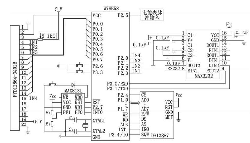
Figure 3 Energy meter reading measurement hardware
DS12887 American DALLAS company introduces 8-bit parallel interface real-time clock/calendar chip, containing 14 bytes of clock and control unit, 114 bytes of user non-volatile RAM, decimal/binary accumulator, bus interface circuit. Built-in lithium battery, able to run for more than ten years without power loss after power failure; with counts of seconds, minutes, hours, days, months, years, and weeks, and a leap year compensation; programmable with binary code or BCD code Represents time, calendar, and alarms; has timer interrupts, periodic interrupts, and clock update cycle end interrupts.
The liquid crystal display module uses 128X64 with Chinese character library is a FYD12864-0402B with 4-digit/8-bit parallel, 2-wire or 3-wire serial multiple interface modes. It contains dot matrix of national standard grade one and two simplified Chinese character library. Graphic LCD module; built 8192 16316 Chinese characters, and 128 1638 ASCII character sets, can also complete the graphic display. The system can also use buttons to query the current power consumption, power consumption and other functions of the month.
4 system software design 4.1 remote meter reading terminal program design The task of the program design is: (1) the user's power collection and processing; (2) TC35I start, status detection; (3) microcontroller and TC5i serial communication; (4) LCD. The system software consists of four parts: the initialization module, the power collection module program, the serial transmission module program, and the display module. The main program flow is shown in Figure 4. 
Figure 4 main program flow chart 
Figure 5TC35i short message sending flow chart. 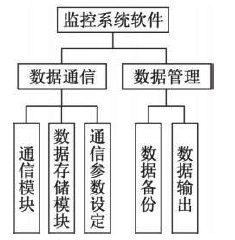
Figure 6 PC software block diagram

Design of wireless power automatic meter reading system based on GSM and single chip microcomputer
Abstract: This paper takes the W78E58 microcontroller as the core to collect the user power data, together with the MAX813L and DS12887 to achieve power-fail detection and data protection. The Siemens TC35i and its peripheral circuits constitute the wireless monitoring communication terminal, using GSM wireless communication network to achieve the user power The data is transmitted to the system center computer and the GSM wireless network remote power automatic meter reading system is realized. The hardware wireless communication terminal of 2GSM wireless communication adopts SIEMENSTC35i as the communication module, and mixes with MAX3232 to realize the conversion of TTL level to RS232 level, as shown in Fig. 2. TC35i is compatible with GSM2/2+, dual band (GSM900/GSMl800), RS232 data port, ETSI standard GSM0707 and GSM0705, and is easy to upgrade to GPRS module. The module has AT command set interface and supports text and PDU mode short message. 3 power meter reading measurement side hardware In this design, power meter reading measurement side to Winbond's microcontroller W78E58 as shown in Figure 3, using MAX813L and S12887 to achieve power-down detection and data protection functions. When working, the MCU only needs to measure the pulses of the single-phase pulse watt-hour meter regularly, and then according to the proportional relationship between the number of pulses and the power consumption, the user's power consumption can be obtained, and the TC35i wireless communication terminal is used to monitor and transmit the user's use. Power to the system center computer. In addition to the manual reset function, the MAX813L also provides reset signals during power-up, power-down, and step-down conditions. When VCC falls below the 4.65V threshold voltage, RST goes high, holding the reset signal for 200ms after VCC rises above the 4.65V threshold voltage; when VCC drops to 1V, the reset output is still guaranteed to be in the correct state. The MAX813L also monitors the system power supply front-end. When the PF1 input is below 1.25V, PF0 outputs a low level to allow the microcontroller to protect the field data through interrupts. Currently, text and PDU (ProtocolDataUnit) modes are commonly used to send short messages. The use of Text mode to send and receive SMS messages is simple and easy to implement. However, the disadvantage is that it cannot send and receive Chinese SMS messages. The PDU mode not only supports Chinese SMS, but also can send SMS messages in English. The PDU mode can send and receive text messages using three types of encoding: 7-bit, 8-bit, and UCS2 encoding. The 7-bit encoding is used to send ordinary ASCII characters, the 8-bit encoding is usually used to send data messages, and the UCS2 encoding is used to send Unicode encoded characters. The software interface between MCU and TC35i is actually the control technology of the MCU through the AT command to control the mobile phone. First, set the working mode of the TC35i module; AT+CMGF=n, n=0 is the PDU mode, n=1 is the text mode; usually it is set as PDU Mode, in this mode, can transmit or receive transparent data (user-defined data). AT+CMGL=n is to read the short message in the TC35i module, n is a short message signal. AT+CMGL=n is a short message listed in the module, a short message that is not read when n=0, n=1 is a short message that has been read, n=2 is an unsent short message, and n=3 is already sent The short message, n=4 for all short messages. AT+CMGL=n is to delete the short message in the TC35i module, n is the short message number. By writing different AT commands through the TC35i, various functions can be accomplished, such as network login, sending SMS messages, and receiving SMS messages. In this system, the serial port communication adopts the interrupt way to realize, its short message sending flow chart is shown as in Fig. 5. 4.2 System Center Computer Software Design This design is based on the overall software design requirements and processes, the entire PC software is divided into two parts: data communication, data management module. In this design, the PC is used as a host computer to communicate with the TC35i through the serial port. The communication software is mainly implemented by using the MSCOMM control of VB6.0. Using VB to create a library file, the PC receives the short message sent by TC35i for data display and storage. The data management part is responsible for data statistics, queries, and database backup and maintenance. The overall block diagram of the system software is shown in Figure 6. 5 Conclusion The adoption of GSM long-range wireless automatic meter reading system has greatly reduced manpower, improved efficiency, improved reliability, reduced costs, provided efficient and scientific management methods for rational use of electricity, and managed the power meter management network for the power sector. Meter reading automation provides an alternative and effective method with good economic and social benefits.