• The installation of the elbow sensor requires the elbow sensor to be mounted on the 90 degree turn of the measuring pipe by means of a welding method. The installation state of the elbow pipe can in principle be arbitrary, that is, the elbow sensor does not have a strict orientation or orientation during installation. Requirements, in general, there are the following four installation states to choose from: â— Horizontal to horizontal; â— Positive pressure measurement on the vertical installation; â— Positive pressure measurement in the vertical installation; â— Any space status. The above four states can be used in principle when installing the elbow sensor. However, for some measured media, selecting the proper installation state can greatly simplify the installation and commissioning work, and it will greatly improve the measurement accuracy of the system. Therefore, it is very important how to correctly select the installation state of the elbow sensor. The following are the specific principles and methods: • For elbow sensors that measure general liquid media, it can be installed in any state. This is because the liquid in the pipe and the liquid in the pressure pipe are in almost the same working conditions. Regardless of the relative position of the two pressure ports of the elbow sensor (refer to the vertical relationship), the differential pressure transmitter does not need to be moved and compensated, so the installation orientation of the elbow sensor is independent of the measurement accuracy of the system. . • For systems that measure hot or cold water (referring to the difference between the liquid temperature in the pipeline and the ambient temperature), if the elbow sensor is not installed horizontally and horizontally, then the two pressure inlets of the elbow sensor are There will inevitably be a height difference H value. Because the liquid in the main pipeline and the liquid in the pressure guiding tube are under different temperature conditions, the density has a certain difference. In order to improve the measurement accuracy of the system, it must be common to this height difference and temperature difference. The differential pressure transmitter's offset value is compensated for migration. The amount of migration can be calculated by the following formula: Δ P = H(Ï 1 -Ï 2 )*g where: ΔP---migration of differential pressure transmitter; H---height difference of two pressure taps; Ï 1 --- Liquid density in the pressure guiding pipe; Ï 2 --- Liquid density in the pipe; g --- Gravity acceleration The specific use of positive or negative migration depends on the orientation of the pipe installation and whether the pipe is hot or cold water. Decision. In the elbow flowmeter, computer automatic transfer compensation technology is used to calculate the fluid density difference between the pressure guiding pipe and the main pipe in real time according to the fixed height difference H value and the measured temperature value, and the difference is directly eliminated from the differential pressure value measured by the differential pressure transmitter. Pressure error. • Installation of elbow sensors for the measurement of steam or other condensable gases. The main considerations for installation here are that these media will condense to liquids at room temperature, which will eventually fill the pressure tube. Therefore, when the elbow sensor is not installed horizontally and horizontally, the height difference of the liquid column in the pressure-inducing pipe due to the height difference between the two pressure-reducing ports must be compensated. The accuracy of this migration compensation is one of the most important conditions for ensuring the accuracy of the measurement system. Because the density of the medium in the process piping is very small (because they are in the state of steam and gas) and the density of the medium in the pressure guiding tube is very large (they are in liquid state), the densities of these two kinds of medium differ greatly, so the differential pressure transmission The migration amount of the device is relatively large, and the elbow sensor is a low differential pressure sensor. The differential pressure value it can generate within the normal operating range is relatively small, so how to ensure the differential pressure transmitter Migration accuracy is very important. • In order to avoid the occurrence of additional measurement errors due to improper migration, the following technical measures are recommended when measuring these media. The disc condenser shall be installed at the pressure inlet of the elbow sensor to ensure the stability of the liquid level of the condensate in the pressure guiding pipe. • As long as the on-site conditions permit, the elbow pipe and the sensor are preferably installed horizontally and horizontally. , Makes the two pressure inlets of the elbow sensor on the same level, fundamentally eliminates the need to compensate for the differential pressure transmitter to migrate; • Because the two pressure inlets of the elbow sensor are on both sides of the elbow, Therefore, it is not easy to accurately ensure that the two disc condensers and pressure taps are on the same level. We hereby provide a simple measurement method for the user to install (see Figure 5). Take a long enough transparent plastic tube to fill the water, and place the two ends of the plastic tube at two pressure measurement ports on both sides of the elbow. Use the horizontal liquid level at both ends of the plastic tube to carefully adjust the disc condenser. Height, it is easy to place the two disc condensers on the same level. • Regardless of the installation method, there is one thing that needs to be complied with. That is, before the system is officially put into operation, the air in the pressure tube and the transmitter must be drained to ensure the correct operation of the system. Therefore, For some systems that measure liquids, a gas-collection tank is required at the highest point of the pressure-guide tube to trap trace gases that may enter the pressure-guide tube during operation. For the same reason, when the equipment is installed, it must be ensured that the horizontally-oriented pressure guiding pipe has a tilt of about 10:1, and the direction of the inclination is to facilitate return of gas to the main pipeline or to facilitate the entry of the gas collection tank.
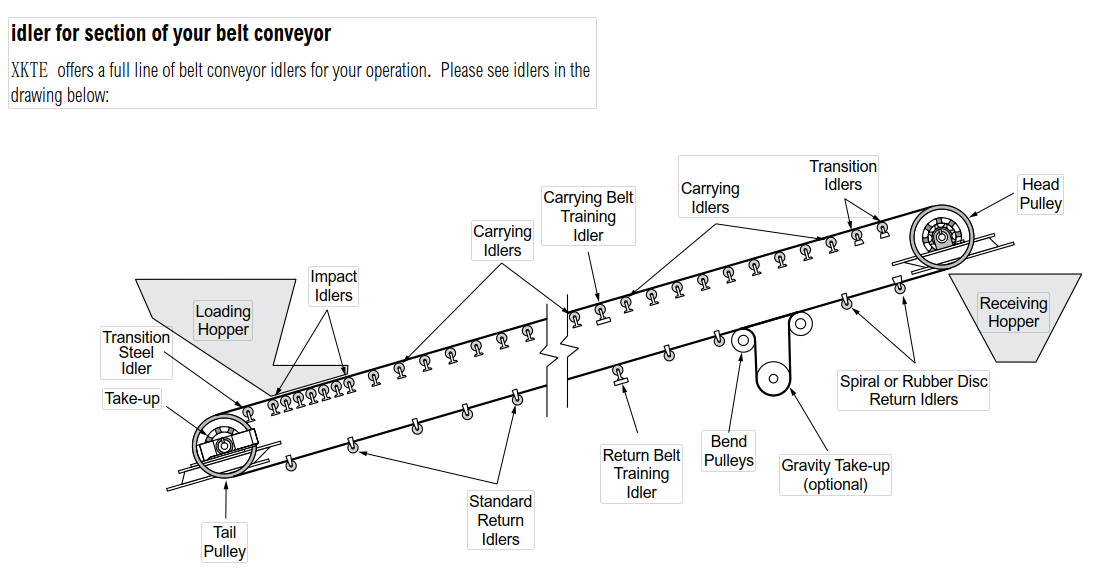
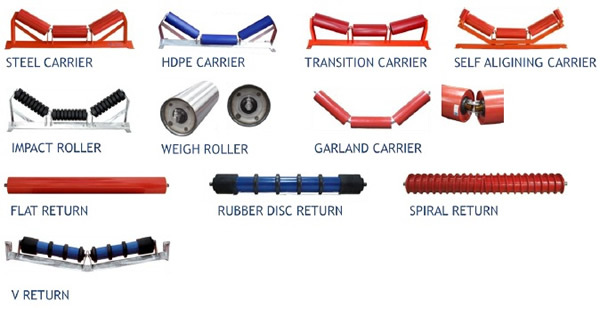
Conveyor idler is the important part of all kinds of belt conveyor, it support the conveyor belt and holds the cargos. Such as Trough Idler, Return Idler, Impact Idler, which meet CEMA, ISO or any other standards. Conveyor idler designs are composed of more than one roller, where various parts of the idler connect to the conveyor belt at different points to keep the belt properly routed and operating well. These designs can also include metal racks for stability.
As a useful part of many industrial systems, conveyor idlers come in many different forms. Some common ones are inline idlers, inset or offset idlers, and return idlers. Inline, inset, and offset varieties are built in very specific ways to accommodate the belt according to optimal factors. Return idlers often deal with the undercarriage of the belt, which moves in the reverse direction. They can help to control aspects of belt return that contributes to the general function of the conveyor belt, such as the width or tension between the top belt and the return.
Conveyor idlers are used to take up extra belt length and provide adjustment for tensioning belt drives. Idler can be valuable belt drive components. bend Idler can alter belt paths, make the belt clear obstructions, or apply belt pre-tension. Idlers may remain in a fixed location, or may be adjustable to allow belt pre-tensioning and take up. Idlers may be applied to either the inside or backside of belts. Backside idlers are generally flat.
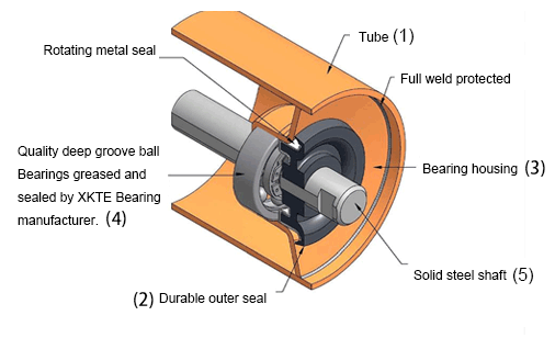
Structure of idler roller:
The internal components of idler rolls are essentially the same
The sealing arrangement protects the bearing from dust and moisture, as well as other environmental contaminants. In addition, the quality of idlers also varies depending on the quality of the individual components and of the manufacturing process. In addition to the idler roll itself, an idler set is supported in position by an idler bracket or base frame. These bases and brackets locate the individual idler rolls relative to each other and provide the necessary 'trough' angle.
1.The outer shells of idler rolls are generally manufactured from 89, 102, 108, 114, 127, 138, 152 and 178 mm tubing.
2.The outer shells are generally closed off with an end cap of varying design.
3. The end caps are normally designed to house the anti-friction bearings (3)
4.and bearing dust seals
5. The anti-friction bearings support the non-rotating idler shaft
The idler shaft has special machined ends to positively location the idler within the base frame support bracket. and every one of our idlers passes through a comprehensive ISO 9001 quality.
Bearing Size
Most manufacturers use 6200 series deep groove ball bearings when constructing B series idlers, and either 6300 series ball bearings or regreasable tapered roller bearings when constructing C series idlers.
Special attention:
For our purposes, most CEMA idler manufacturers publish life expectations for 30,000 hours L10 life at 500 RPM.
Diameter of roller mm
Length of roller(tube)mm
Bearing
89
190.200.230.240.280.305.315.375.380.455.465.600.750.950.1150
6204
108
190.200.240.250.305.315.375.380.455.465.525.600.700.750.800.950.1150.1400
6205
133
305.350.375.380.455.465.525.530.600.700.790.800.950.1150.1400.1600
6305
159
375.380.455.465.525.630.600.640.670.700.750.790.800.900.950.1050.1120.1150.1400.1600
6306 6308
193.7
600.640.750.800.900.950.1050.1120
217
600.640.1050.1120
Conveyor Idler,Conveyor Idler Roller,Belt Conveyor Idler,Conveyor Carrier Idler Shandong Xinkaite Bearing Co., Ltd. , https://www.idlerbearing.nl


